

|
This is the page where I try to apply my expertise as a flight instructor to issues that need some clarification, or review. I know that as regulations or procedures change we all need a little help in understanding how changes effect us. Sometimes we think we understand some particular concept or procedure only to find out that maybe we don't understand it like we think we should.
|
|
Instrument flying is not a physical excercise it is a mental one. To fly instrument successfully one must be able to do four things: Fly the airplane solely by reference to the instruments, navigate, communicate, and do all these things simultaneously.
A "frazzeled" pilot is one who was not well trained, is not well diciplined, and does not stay current, and as a result must devote so much mental resources flying the airplane that he or she does not have enough time to devote to the other required tasks. "Frazzeled pilots have little or no brain space left to consider alternatives when faced with a problem. Almost all of their attention is spent simply flying the aircraft. So they listen to others instead of making the decisions themselves. And others cannot make the decisions. A controller may offer a solution to a pilot, but only the pilot can judge whether it is best for that situation or not. Other pilots flying other airplanes may advance suggestions, but deciding on the spot that something is the right thing to do only because it sounds good can lead to disaster. Without giving any course of action the proper degree of thought a pilot gives up much of his or her authority. (It is at this point that) events, instead of the pilot, begin controlling the situation." Brian M. Jacobson - "Flying on the Gages" |
|
"CLARIFYING DEPARTURE PROCEDURES, or DP's." If you use Jeppesen charts, in the lower left-hand corner of the airport chart is a textual description of an OBSTACLE DEPARTURE PROCEDURE, or ODP, for that airport. If you use NACO charts these textuals are listed in aphabetical order in the front of the applicable Terminal Procedures book on a page entitled "TAKE-OFF MINIMUMS AND (OBSTACLE) DEPARTURE PROCEDURES". Don't confuse ODP's with Standard Instrument Departures or SID's. SID's are designed to increase capacity of the terminal airspace, effectively control the flow of traffic with minimal communication, and reduce environmental impact through noise abatement procedures in busy terminal areas. While obstacle clearance is always a consideration in SID routing, the primary goal is to reduce ATC/pilot workload while providing seamless transitions into the enroute structure.
WHAT DO THESE PROCEDURES DO FOR YOU? Departure procedures are preplanned routes that provide transitions from the departure airport to the enroute structure. These procedures are primarily designed to provide obstacle clearance for departing aircraft. They also allow for efficient routing of traffic and pilot/controller workload. In this discussion we will concern ourselves only with the Obstacle Departure Procedure, or ODP.
STANDARD ODP DESIGN CRITERIA The design of a departure, be it a SID or an ODP, is based on TERPS criteria. The new TERPS criteria establishes an Obstacle Clearance Surface (OCS), or plane, which starts at the Departure End of the Runway (DER) with a slope of 40:1. This surface slopes up at 152 feet per Nautical Mile (NM) which is equivalent to 2.5%. To provide at least 48 feet per NM of Required Obstacle Clearance (ROC) with obstacles that do not penetrate the OCS a minimum of 200 feet per NM climb gradient, or 3.3%, is required. The ROC value is therefore zero at the DER elevation and increases until the appropriate ROC value is attained upon entering the enroute structure. This typically extends the ODP to approximately 25 NM for 1000 feet of ROC in non-mountinous areas, to approximately 46 NM for 2000 feet of ROC in mountinous terrain. The ODP must also include Positive Course Guidance (PCG) typically within 5 to 10 NM of the DER for straight out departures and within 5 NM after turn completion on departures requiring a turn. Even when aircraft performance greatly exceeds the minimum 200 feet per NM (3.3%), the published routing must always be flown.
NON-STANDARD ODP'S In a perfect world, the standard 40:1 slope of the OCS would work for every location, however, due to terrain or man-made obstacles, it is sometimes necessary to require climb gradients greater than 200 feet per NM in order to provide safe clearance with obstacles. The required higher climb gradient in this case is based on what's called the ROC 24 percent rule. To keep the ROC ratio the same as the standard, when the required climb gradient is greater than 200 feet per NM, 24 percent of the total height above the starting elevation, i.e. the DER in MSL, gained by a departing aircraft to a minimum altitude, in MSL, required to clear an obstacle that penetrates the OCS, is the ROC. This is determined by the following formula: Climb Gradient (in feet per NM) = Obstacle height (in MSL) − Starting elevation (in MSL) ÷ 0.76 × the distance from DER to obstacle (in NM) Example: 2049 − 1221 ÷ 0.76 × 3.1 = 351.44 or 352 ft/NM (rounded) Obstacles located within 1 NM of the DER and which penetrate the 40:1 OCS are referred to as "low, close-in obstacles." Obstacles of this type would require an excessive climb gradient for a very short distance. To eliminate the need to publish an excessive climb gradient, the AGL/MSL height and location relative to the DER is noted in the Take-off Minimums and (OBSTACLE) Departure Procedure. In addition, higher than standard take-off minimums may be listed which allow the pilot to see and avoid these obstacles. The Obstacle Departure Procedure for Aspen, Colorado is a good example:
ASPEN,CO ASPEN-PITKIN COUNTY/SARDY FIELD TAKE-OFF MINIMUMS: Rwy15, N/A. Rwy33, 3100-3 or 1000-2 with a min climb of 480' per NM to 14000. DEPARTURE PROCEDURE: Climb heading 340° to 8700, then climbing left turn to 16000 heading 270° to intercept and proceed via i-PKN northwest course outbound on backcourse and DBL,R-244 outbound to GLENO int/DBL,22.7DME. Climb in GLENO holding pattern (SW,left turns, 064° inbound) to cross GLENO at 16000 before proceeding in route. NOTE: Rwy33, 6179' tree 3447' from departure end of runway, 1379' left of centerline.
...AND, FINALLY ODP's are for obstacle clearance only. ODP's are only established at airports that have Instrument Approach Procedures (IAP) The design of ODPs does NOT take into consideration the performance of the aircraft; it only considers obstacle protection. It is the pilot's responsibility to calculate aircraft performance, particularly when flying of airports at high pressure/density altitudes on warm days. Even if your aircraft performance greatly exceeds the published minimum climb gradient the published routing of the ODP must be flown. Pilots do not need ATC clearance to use an ODP and they are responsible for determining if the departcure airport has this type of published procedure. Textual ODPs are only issued by ATC controllers when required for traffic. If they are not issued by ATC, textual ODPs are at the pilot's option to fly or not to fly, even in less than VFR weather conditions, for Part 91 operators. If you intend to use a published ODP it is recommended that "Will depart (airport) (runway) via textual ODP" be entered in the remarks section of your flight plan to prevent potential pilot/controller misunderstanding.
|
|
"HOW FAST ARE WE GO'IN?" All of us who fly for a living have had a passenger stick his (or her) head in the cockpit and say, "Hey, how fast are we going?". Just, what number does that passenger want anyway? In knots or in miles per hour? I don't always know but let's look at the options. INDICATED AIRSPEED The most obvious choice is probably the airspeed under the needle on the airspeed indicator, or, the indicated airspeed (IAS). The airspeed indicator is actually a pressure gauge. The scale on the face of the gauge, instead of being calibrated in pounds per square inch of pressure, or some equivalent, is calibrated in speed corresponding to a given pressure. This pressure is sensed by a tube pointing forward into the flight path. The faster the airplane goes the higher the pressure in the tube and the higher the "speed" indicated on the guage. The tube is called a Pitot(pronounced pee-tow) tube because this method of measuring speed was invented by Henri Pitot, a French physicist. The Pitot tubes can be a single aluminum tube protruding from the wing leading edge such as those on low performance airplanes. When the airplane is on the ground the gauge is calibrated to read zero airspeed. However, the pressure measured by the tube is the atmospheric pressure. The airspeed system will not give an accurate indication of airspeed unless the static pressure is accounted for. For this reason there are also one or more static ports connected to the airspeed indicator. The pressure measured is then the difference between the pressure in the Pitot tube generated by the airplane's forward speed, and the static pressure. This then gives us an indication of airspeed that is as accurate as it can be measured. In the interest of accuracy, the Pitot tubes are located in a position on the airplane so that the air coming off of the airplane does not effect the pressure they sense. The static ports are simply holes located in the side of the fuselage in an area of neutral pressure. If the air flowing past the airplane is rammed into the ports the static pressure will read higher than the actual static pressure; if the air flowing over the ports causes a suction in the tube connecting it to the airspeed indicator the static pressure will be lower than the actual static pressure. Finding just the right location for the Pitot tube(or tubes), and especially for the static ports, can be a very dificult and time consuming task during initial flight tests. High performance airplanes usually have more than one Pitot tube mounted on the nose, one for the pilot's airspeed, one for the co-pilot's airspeed, and sometime's a third for the standby airspeed. The static ports are holes drilled into the sides of the Pitot tubes on these high performance airplanes. The Pitot tubes installed on airplanes certified to fly in Instrument Meterological Conditions(IMC) are heated to prevent ice from plugging them up. The Pitot heat on these airplanes is on all the time while in flight and the tubes turn a bluish-brown color. If you happen to be flying a jet your airspeed indicator will also have a moving scale that shows your IAS in Mach(Earnst Mach - 1836-1916) . The Mach number is simply your speed relative to the speed of sound and is strictly a function of the temperature of the air in which you are flying. As the altitude increases the temperature decreases; as the temperature decreases the speed of sound decreases. The speed of sound at a given altitude(temperature) is Mach one. If the indicated Mach is 78 then you are traveling at 78% of the speed of sound. The speed of sound at sea level in a standard atmosphere(temperature 59 degrees F) is approximately 660 knots; at 35,000 feet(temperature -66 degrees F) it is aproximately 575 knots. Factors such as non-standard atmospheric conditions, instrument errors, the installation configuration, and compressibility effects, may cause a variance between the airspeed indications and the actual flight speed.
CALIBRATED AIRSPEED Calibrated airspeed (CAS) is the result of correcting IAS for errors in the airspeed instrument and errors due to position or location of the installation. Each aircraft type has a Pitot static system that is unique to that type. Instrument errors must be small by design and are usually negligible if the instrument is properly maintained. Position errors are most usually confined to the static system and must be small in the range of airspeeds for the most critical or common performance condition. The most critical or common performance condition in corporate and personal airplanes is cruise.
EQUIVALENT AIRSPEED Equivalent airspeed is the result of correcting the CAS for compressibliity effects. At high flight speeds compressibility of the airflow recovered in the Pitot tube produces a pressure which is greater than if the airflow were incompressible. This causes an erroneous airspeed indication.
TRUE AIRSPEED True airspeed is the speed of the airplane through the block of air in which it is operating. The airspeed indicator is calibrated for airspeeds corresponding to the dynamic pressure at sea level in the standard atmosphere, i.e. at sea level in the standard atmosphere the IAS and the TAS will be the same. However, as a practical matter the airplane operates in a non-standard atmosphere all of the time. Therefore, the TAS must be calculated using the EAS and the density altitude. The density altitude is the altitude in the standard atmosphere corresponding to a particular value of air density. Density altitude is computed using the pressure altitude(PA) - the pressure in the standard atmosphere corresponding to a particular pressure - and, the temperature at that altitude.
GROUND AIRSPEED The ground speed is the speed of the airplane over, or relative to, the ground. As we have already seen the airplane is flying through a block of air at a given true airspeed. However, the block of air in which the airplane is operating is also moving, due to the speed and direction of the wind. To get the ground speed we must add, or subtract, the headwind, or tailwind, component of the speed of this block of air to/from the TAS. It is important to note that since the TAS is a measure of the airplane's speed through the block of air in which it is operating, that the TAS is the same regardless of which way or how fast this block of air is moving. To visualize true airspeed and ground speed think of a fish swiming in a tank. The fish is swimming in a block of water the size of the tank. If the fish represents an airplane and the water in the tank represents the block of air in which the airplane is flying then the speed of the fish through the water in the tank represents the true airspeed. Now, if we put the fish tank in the back of a pickup truck and drive down the road at, say, 60 mph the speed of the truck represents the wind speed. If we then add, or subtract, the "wind speed" component to the "true airspeed" of the fish in the tank we will get the ground speed. If the fish happens to be swimming in the tank in exactly the same direction the the truck is traveling then the ground speed is the speed of the fish plus the speed of the truck. If the fish is swimming exactly opposite the direction the truck is traveling then the ground speed is the speed of the fish minus the speed of the truck. Otherwise, the "ground speed" is the speed of the fish plus or minus some fraction of the "wind speed" depending on the angle between the direction of travel of the fish in the tank and the direction of travel of the truck. After all of this measuring, correcting, and calculating the speed that is the most useful to us, then, is the ground speed. The ground speed is what determines how long it will take to get to our destination, and what time we will get there. You're answer to that passenger should then be something like this, "Our speed over the ground right now is 520 knots, or 600 miles per hour. This will put us in (destination) in (ETE) at (time) local time." |
|
"V1 SPEED MAY NOT BE WHAT YOU THINK IT IS!" The jet pilots reading this will probably recall that the V1 threshold speed during takeoff was, a few years back, and often times even today, defined as the "Take-off decision speed". Instructors usually told us that this was the speed at which we must make a decision either to take-off or stop on the remaining runway after an engine failure. The Take-off Field Length (TOFL) which is the longest of:
1. 115% of the normal two-engine take-off distance taken from the TOFL charts in the Airplane Flight Manual (AFM) will allow for this choice since the TOFL is the most restrictive (the longest) of these three distances. It should be noted that it is unlikely that any two of these speeds will match for any given set of conditions. Let's take a look at the definition of V1 provided by some light and medium-jet AFM's:
"V1 - Take-off Decision Speed - The maximum speed below which the pilot must initiate the first action (brake application) to discontinue a takoff. Above V1 the takeoff must be continued. Varies with weight, temperature, altitude, runway gradient, and operation of Anti-skid and Anti-Ice."Is there any wonder that there is at least some confusion as to what V1 speed means and how it should be applied? Three out of the five definitions start off with "Take-off Decision Speed." The remaining two call V1 the "...engine failure speed." The Hawker 400 definition specifies "...the pilot must initiate the first action (brake application)..." prior to V1 to "...discontinue a takeoff." How can V1 be the "...decision speed" if the pilot must "...initiate the first action..." before "(The) Take-off Decision Speed (V1)."? The manual for the Lear 60 states that the "...distance to continue the takeoff to 35 feet or...to stop..." will no exceed the ...scheduled takeoff distance (presumably the TOFL)...(if) the brakes are applied at V1." This is not the same definition provided for their own 35/36A. The definition provided for the 35/36A seems to include the definition of "Balanced Field Length." (A Balanced Field Length, or BFL, is when the Accelerate-Stop and Accelerate-Go distances are the same.) Reading these definitions one could conclude that perhaps V1 is a "...decision speed to..." continue the takeoff but that the decision to stop on the runway must be made "...prior to..." V1. However, two of the definitions say, "Above V1 the takeoff must be continued." while the others say that the pilot has a choice to "...bring the airplane to a full stop..." at V1. In all of the definitions the reason for a "...decision..." is based on an engine failure only. To help clear this up read this discussion of V(sub)1(/sub) from "When the Engine Goes 'Bang'", by Patrick B. Veillette, Ph.D., Business & Commercial Aviation, July 2006:
There is a great deal of misunderstanding regarding the definition and use of the V1 speed. Years of inconsistant terminology in reference to V1 has probably contributed to this confusion. V1 therefore, is indeed a decision speed but only for continuing the takeoff. Above V1 a rejected take off (RTO) is not an option. V1 cannot be the decision speed for a rejected takeoff if it is to be defined as the "...the maximum speed at which the pilot must take the first action (e.g., apply brakes, reduce thrust, deploy speed brakes) to stop the airplane...". Another V-speed Vef, or the critical engine failure speed, has been established which represents the decision speed for an RTO. Remember that by definition the reason for a rejected takeoff is always assumed to be an engine failure although the majority of RTO's are statistically not for an engine failure. The FAA defines Vef in FAR Part 1 as, "...the speed at which the critical engine is assumed to fail during takeoff." Indeed if we look at the requirements to achieve the published Accelerate-Stop-Distance in the manufacturers AFM for one of the airplanes cited above the second requirement is: (b) The pilot recognizes the necessity to stop because of an engine failure or other reasons just prior to V1 (emphasis mine). Think about it, V1 may not be what you thought it was. * If you would like a PDF copy of the Takeoff Safety Training Aid, CLICK HERE | ||
 |
January 1, 2002 | |
 Seemingly for generations pilots have argued over which controls speed and which controls altitude: power or pitch. At varing times the FAA contributed support to both sides with publications outlining flying techniques and training information. The vary existence of the arguably adolesent-level debates ignores the hard reality: In powered aircraft neither one works alone. To achieve optimum performance in any setting requires balancing the two to best match the needs of the moment.
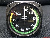 One of the most coveted, and best known tomes on aviating, Wolfgang Langewieshe's Stick and Rudder, is approaching 70 years old. That's been in continuous publication since it left the presses in 1944 is a testament to it's importance and revelance.
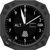 Now consider the opposite - you leave pitch alone and change power. Power, of course, provides pilots with the luxury of changing altitude almost at will and to span large distances unconcerned with working lift to stay aloft. For any given power setting, the pitch angle determines whether you climb, cruise in level flight or descend. That's because for every power setting there is a matching pitch attitude - or airspeed - allowing either the conversion of power into more altitude, to faster level flight or to a reduced altitude.
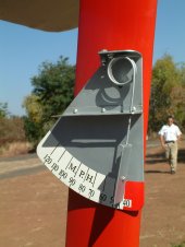 Now start trimming the nose up, gradually. If you continue to apply nose-up trim, presuming your airplane has sufficient trim auththority, eventually you'll either stall or arrive at the mush state that is as close to a stall as many aircraft get. The difference? With the cruise-power setting, the pitch change took you from the fastest the plane can fly to the slowest. Only the pitch attitude was changed. Yes, you gained altitude in the process, because power controls altitude in this scenero, while the airplane progressively slowed as the pitch angle increased.
 In aircraft blessed by experiencing little or no pitch change with flaps and gear out , we'll need more power to hold that altitude - or if ATC allows, we can let the excess drag pull us down, still at that the trimmed airspeed.